
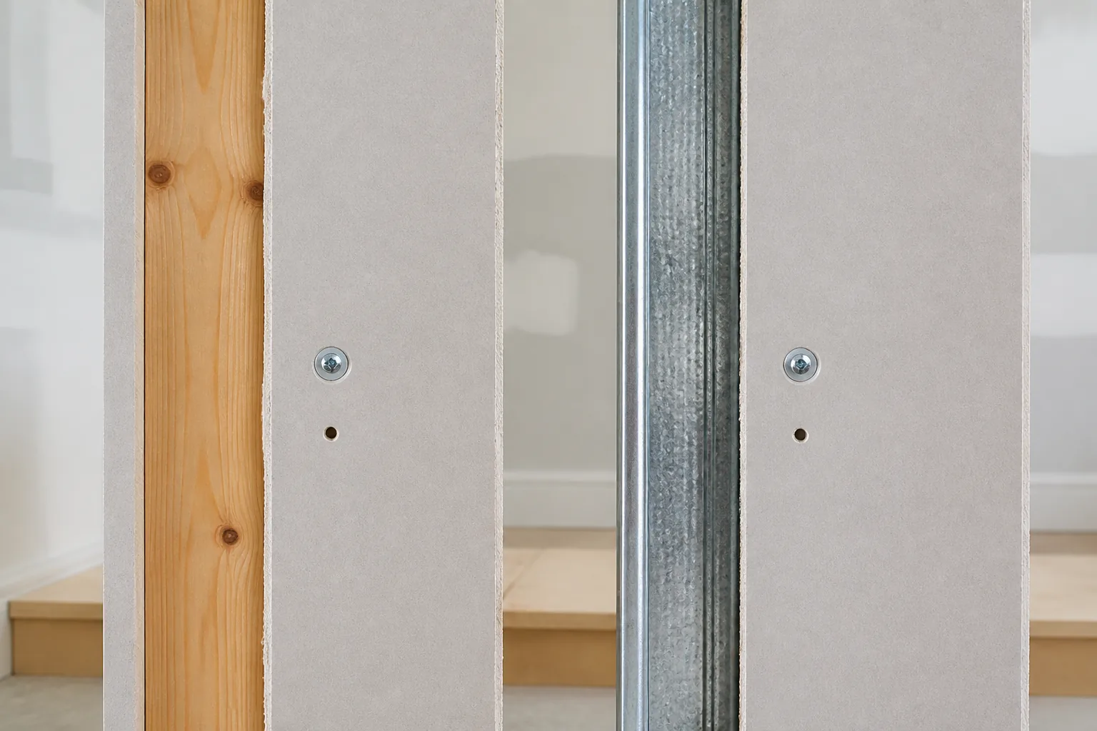
The short answer: wood and metal need different mounting plans
A screw into a wood stud develops thread engagement through solid wood. A screw into a cold-formed steel stud engages a comparatively thin steel flange unless the attachment uses a toggle, backing or another designed connection. That difference—not a simple claim that one stud is stronger—controls the mounting decision.
In most U.S. light-frame wall discussions, “metal stud” means a cold-formed, metallic-coated sheet-steel member. The American Iron and Steel Institute describes these products as roll-formed steel studs, tracks and related components. Aluminum is not the ordinary substitute meant by residential “metal stud,” so an “aluminum studs vs. wood” search should first verify the material rather than assume aluminum.
| What to compare | Wood stud | Cold-formed steel stud |
|---|---|---|
| What the fastener engages | A length of solid wood | A thin flange, backing or a listed hollow-wall connection |
| Useful identification clues | Grain at a safe exposed edge; density change; construction records | Repeated vertical metal response; visible C-shaped framing; system labels or drawings |
| Mounting information needed | Pilot diameter, minimum wood embedment and clear utility path | Member thickness/designation, flange location, cavity and approved fastener system |
| Common wrong assumption | Every wood signal is a full dimensional stud | Any self-drilling screw or wood lag is suitable |
| When to escalate | Engineered member, damaged framing or high-consequence load | Unknown thickness, unknown backing or cantilevered/high-consequence load |
Know which kind of stud or backing you found
The American Wood Council describes wall studs as vertical members and notes that exterior studs in one- and two-story buildings are at least nominal 2×4 lumber. Cold-formed steel wall framing commonly uses lipped C-shaped studs fitted into top and bottom track. The AISI overview says 16- or 24-inch on-center layouts are typical, but actual spacing can vary with loads and coverings.
Those common U.S. dimensions are orientation clues, not proof of what is behind one finished wall. A signal could also be engineered wood, a doubled stud, short wood blocking, steel furring over masonry, track, a protective plate, a pipe or a duct. Measure several bays and verify an edge or record before choosing hardware.
- Dimensional or engineered wood stud
- Cold-formed steel C-stud
- Wood blocking inside a steel-framed wall
- Furring attached to masonry
- Track, backing plate or utility-protection plate—not a stud
Read steel labels instead of guessing from gauge
Cold-formed steel members are not all the same thickness. The AISI overview gives a broad product range from 0.0147 inch to about 1/8 inch, covering nonstructural and structural products that behave very differently. The 2026 SFIA guide identifies stud sections with the letter S and expresses minimum base-metal thickness in mils; for example, 54 mil means 0.054 inch.
Do not convert a casual “gauge” description into mounting capacity. Product designation, base-metal thickness, yield strength, fastener data, wall layers, flange width and connection geometry can all matter. If the mount instructions require a known steel specification and no label, drawing or qualified assessment establishes it, that fastening path remains unverified.
- Look for drawings, submittals or an exposed member label
- Record the complete designation rather than only a gauge number
- Check whether the member is structural or nonstructural
- Match the exact fastener instructions to the documented assembly
Look for converging identification clues
Magnetic detection may indicate metal framing or simply rows of drywall screws. An exposed utility area, construction documents, a known wall system or a carefully observed existing edge provides stronger evidence. Electronic tools can be confused by foil, mesh, pipes and wiring.
Wood studs may create a narrower density change, while metal studs can produce a strong vertical metal response. Neither signature is universal. Confirm more than one location and account for wood blocking that may be installed within an otherwise metal-framed wall.
- Construction records
- Safe exposed framing
- Repeated edge pattern
- Magnetic response
- Known blocking locations
Use this mounting decision path
First read the object or bracket instructions and list every approved substrate. Next verify the wall finish and framing at every proposed hole. Then compare the required fastener, minimum engagement, hole size, spacing, edge distance and cavity against the actual assembly. Only continue when the complete connection—not merely the stud location—matches a documented method.
A nearby stud is not automatically usable if the bracket holes cannot align as required. Likewise, adding more anchors does not automatically multiply capacity; holes can share a damaged area and loads rarely divide perfectly. Change the bracket position, add purpose-designed backing or obtain qualified help when the required geometry cannot be met.
- 1. Record the full installed load and how it moves
- 2. Read the mount maker’s approved substrates
- 3. Verify finish layers, framing and every hole location
- 4. Match the exact fastener system and clearances
- 5. Stop if any required fact remains unknown
Plan a wood-stud attachment
Use the mount manufacturer’s required screw, pilot hole and minimum wood embedment. Subtract drywall, brackets, washers and spacers from the usable fastener length. Mark both stud edges, aim for the required location within the stud and control depth rather than assuming a longer screw is safer.
Check for splitting, knots, engineered members and unexpected voids. Do not assume every detected wood element is a full stud; furring, blocking and trim backing can have different dimensions. An unexpected hard stop can be a protection plate, not confirmation that the fastener has reached stronger material.
- Mark and verify both stud edges
- Use the specified pilot diameter and depth
- Calculate actual wood embedment after every finish layer
- Avoid unnecessary fastener length
- Stop at unexpected resistance
Plan a cold-formed steel attachment
Start with the object and mount instructions. A documented approach may use a screw selected for a known steel thickness, a toggle through the complete wall assembly, a multi-stud mounting plate, manufacturer-specified backing or added blocking. These are different connection systems; one method’s rating cannot be transferred to another.
Check the required clear cavity behind the wall before using any toggle-style device. Verify flange width, member thickness and the number of studs the bracket must span when the instructions make those details conditions of use. Full-motion mounts, grab bars, overhead items and other high-consequence loads should not be improvised on an unknown steel partition.
- Verify the member designation or thickness when required
- Confirm clear cavity and every wall layer
- Use the listed screw, toggle or backing geometry
- Distribute the load only as the mounting system specifies
- Use qualified evaluation for unknown or high-consequence assemblies
Recognize the failure signals before loading the mount
In wood, a pilot hole that never develops expected resistance may have missed the stud, entered a void or stripped damaged material. Excessive torque can split wood or damage threads. In thin steel, a screw that continues spinning may have stripped the flange; increasing screw size without an approved detail does not restore a known connection.
For either assembly, torn drywall paper, a crushed surface, a bracket that rocks, fasteners that cannot be brought up evenly or different materials at different holes are reasons to stop. Remove or independently support the object and reassess the wall rather than treating a tight-looking bracket as a load test.
- Fastener spins without reaching the specified set
- Bracket dimples or crushes the wall finish
- One hole encounters a different material
- Cracking, popping or movement appears during a controlled check
- Instructions and observed assembly no longer agree
Protect concealed wiring and plumbing
OSHA’s electrical-safety rule for construction requires determining whether exposed or concealed energized circuits are positioned where work could contact them. A home DIY project is not a substitute for that workplace rule, but the hazard is the same: a drill or fastener can reach wiring that is invisible from the room.
Do not infer a clear path from a stud finder alone. Review both sides of the wall, nearby outlets, switches and plumbing fixtures; use appropriate detection methods; control drilling depth; and stop at unexpected metal or resistance. Do not drill through a plate to find out what it protects. If safe routing cannot be established, relocate or use a qualified professional.
- De-energize relevant circuits when the work plan calls for it
- Inspect both sides and nearby service locations
- Use depth control
- Treat unexpected plates and resistance as stop signals
Avoid hybrid assumptions
A wall can contain metal studs with wood blocking, wood studs with metal protection plates, or furring over masonry. One detected section does not describe the entire wall. Map the intended fastener locations individually.
If different holes encounter different materials, stop and reconcile the wall assembly with the mounting instructions. Mixing fastener types can be valid only when the engineered system allows it and each connection has a defined role.
Frequently asked questions
Are residential metal studs aluminum?
Usually no. U.S. light-frame “metal studs” are ordinarily cold-formed, metallic-coated sheet-steel members. Verify the actual product or building records before selecting hardware.
Are wood studs better than metal studs for mounting?
Neither is universally better. Wood can provide solid thread engagement, while a verified steel wall can use purpose-designed screws, toggles or backing. The approved connection and complete wall assembly decide.
What types of studs might be behind drywall?
Common possibilities include dimensional or engineered wood, cold-formed steel, doubled members, short blocking and furring over another base. Track, plates, pipes and ducts can also mimic a stud signal.
Can a regular stud finder detect metal studs?
Some can, but readings may also come from screws, pipes or mesh. Confirm using another method.
Can lag screws be used in light-gauge steel studs?
Do not assume so. Use a fastening method explicitly approved for the known steel framing and mount.
Can metal-stud walls contain wood?
Yes. Blocking or door and cabinet backing may be wood, which is why each mounting location needs verification.
A practical next step
Before buying hardware, confirm the wall assembly and read the installation instructions for both the object and the exact fastener. If you need a starting category, use our Anchor Selector.
Sources and further reading
These primary and manufacturer resources support the safety and installation principles summarized above. Always use the current instructions for your exact product.
- Lumber Studs — American Wood Council
- Cold-Formed Steel Framing — American Iron and Steel Institute
- Technical Guide for Cold-Formed Steel Framing Products — Steel Framing Industry Association
- Sheetrock Installation and Finishing Guide — USG
- General Electrical Safety Requirements — Occupational Safety and Health Administration